Design Guide: The Rules We Work To
The numbers behind every part we make, from corner radii and threads to fits, finishes and coatings. Free to use on your own drawings.
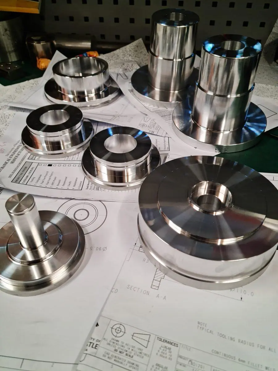
These are the numbers we design and machine to every day. Use them to draw parts that are quicker and cheaper to make, and to know exactly what standard your part is built to.
Every figure was cross-checked against at least two published sources (ISO, DIN and manufacturer data), and every formula was checked numerically. Where reputable sources disagree, we give the range.
Drawing defaults
What you get when your drawing doesn’t say otherwise.
Table below. Tighten only the 3–5 features that matter.
One note on the drawing covers it. No need to dimension every chamfer.
Threads start clean and don’t burr.
Coastal air rusts bare steel overnight.
The standard measuring temperature. A hot part isn’t on size yet.
Pockets, corners and walls
The cheapest part is the one a big cutter can reach.
Tighter means a long, skinny cutter that bends and chatters.
Bigger corners let a bigger, faster cutter do the work.
Steel / aluminium / plastic. Thinner walls vibrate and move.
A slot at least a quarter as wide as it is deep.
Odd or full-ball floors need slow 3D finishing.
Top, bottom and four sides. Odd angles cost extra time.
- One internal radius everywhere on the part. Every extra radius is another tool and another toolpath.
- Undercuts: standard T-slot and 45° or 60° dovetail shapes only.
- Engraved text: at least 5 mm high, strokes at least 0.5 mm wide and about 0.3 mm deep (0.84 mm wide in hard metals).
Holes and threads
Standard sizes, sensible depths, room to finish the thread.
M6 → 5.0 · M8 → 6.8 · M10 → 8.5. About 75 % thread, which is the target.
Up to 10×D is fine. Deeper is specialist work.
Never call up “thread to bottom” in a blind hole.
Centre to edge, 2×D preferred. A boss wants an OD of 2.5×D.
Metric holes (mm)
| Thread | Tap drill | Clearance close | Normal | Loose | Cap screw c’bore | C’sink Ø 90° |
|---|---|---|---|---|---|---|
| M3 | 2.5 | 3.2 | 3.4 | 3.6 | Ø6.5 × 3 | 6.0 |
| M4 | 3.3 | 4.3 | 4.5 | 4.8 | Ø8.25 × 4 | 8.0 |
| M5 | 4.2 | 5.3 | 5.5 | 5.8 | Ø9.75 × 5 | 10.0 |
| M6 | 5.0 | 6.4 | 6.6 | 7.0 | Ø11.2 × 6 | 12.0 |
| M8 | 6.8 | 8.4 | 9.0 | 10.0 | Ø14.5 × 8 | 16.0 |
| M10 | 8.5 | 10.5 | 11.0 | 12.0 | Ø17.5 × 10 | 20.0 |
| M12 | 10.2 | 13.0 | 13.5 | 14.5 | Ø19.5 × 12 | — |
| M16 | 14.0 | 17.0 | 17.5 | 18.5 | Ø25.5 × 16 | — |
- Thread depth by material: 1×D steel · 1.25×D cast iron · 1.5×D 6061 aluminium · 2×D soft or cast aluminium · 2.5–3×D plastic. Past about 1.5×D the bolt breaks before the thread strips.
- Standard drill sizes only. An odd diameter has to be milled or bored instead.
- Flat-bottom blind holes are a second operation. Only call one up if the flat bottom does a job.
- Hole accuracy: drilled ±0.05–0.15 mm · reamed H7 · bored H6–H7.
- Countersinks are cut 0.2–0.3 mm deeper than nominal so the head never sits proud.
- Helicoil (STI) inserts: tap drill ≈ nominal + 0.1×D (M6 → 6.3, M8 → 8.4). Use an insert 1.5×D long.
Tolerances
Only tolerance what matters. Every tight number costs money.
Below about ±0.05 mm, cost roughly doubles every time a tolerance is halved.
Features that line up hold best when they’re cut without turning the part over.
Milled / ground.
±0.01 mm needs a gauge that reads to 0.002 mm.
ISO 2768 general tolerances
| Size (mm) | f (fine) | m (medium) | c (coarse) |
|---|---|---|---|
| 0.5–3 | ±0.05 | ±0.1 | ±0.3 |
| 3–6 | ±0.1 | ±0.2 | ±0.5 |
| 6–30 | ±0.15 | ±0.3 | ±0.8 |
| 30–120 | ±0.2 | ±0.5 | ±1.2 |
| 120–400 | ±0.3 | ±0.8 | ±2.0 |
| 400–1000 | ±0.5 | ±1.2 | ±3.0 |
What’s realistic by process (mm) — typical across the trade
| Process | Typical | ISO grade |
|---|---|---|
| Turning | ±0.02–0.05 | IT7–IT9 |
| Milling | ±0.025–0.10 | IT8–IT10 |
| Boring | ±0.01 | IT6–IT7 |
| Reaming | H7 | IT7 |
| Cylindrical grinding | ±0.005 | IT5–IT6 |
| Surface grinding | ±0.005 | — |
- Angles (ISO 2768-m): ±1° on legs to 10 mm · ±30′ to 50 mm · ±20′ to 120 mm · ±10′ to 400 mm.
- Worst-case stack-up = add every tolerance in the chain. Use it for one-offs, small batches and anything safety-critical.
- Statistical (RSS) stacking needs 4+ independent dimensions on a well-centred process. Five ±0.1 dimensions give ±0.22 instead of ±0.5. Tempting, but wrong if the process drifts.
- Datum A is the face the part sits on in service, not whichever face is easiest to draw from.
- Use position with datums for anything that assembles. A round position zone gives about 57 % more room than the same ± box.
- Add MMC (Ⓜ) to clearance-hole patterns. Bigger holes earn extra position tolerance for free.
Fits, bearings and dowels
Hole-basis: the bore is H7 and the shaft is sized to get the fit.
Always clearance.
Assembles by hand.
Tap together with a mallet.
Arbor press.
Needs a press.
Carries torque without a key.
ISO 286 limits
| Fit (µm) | Ø10 | Ø25 | Ø50 | Ø100 |
|---|---|---|---|---|
| H7 hole | +15/0 | +21/0 | +25/0 | +35/0 |
| g6 shaft | −5/−14 | −7/−20 | −9/−25 | −12/−34 |
| h6 shaft | 0/−9 | 0/−13 | 0/−16 | 0/−22 |
| k6 shaft | +10/+1 | +15/+2 | +18/+2 | +25/+3 |
| n6 shaft | +19/+10 | +28/+15 | +33/+17 | +45/+23 |
| p6 shaft | +24/+15 | +35/+22 | +42/+26 | +59/+37 |
| s6 shaft | +32/+23 | +48/+35 | +59/+43 | +93/+71 |
Press fits and bearings
0.025 mm on Ø25, steel on steel. Double it for shock loads or thin hubs.
m5/m6 for heavy or shock loads. Housing H7.
Split housings are always H7.
The other must float, or heat growth preloads the bearing.
Dowels, keys and circlips
- Locate with two dowels, clamp with bolts. Bolts in clearance holes leave 0.2–0.5 mm of play; dowels hold about 0.01 mm.
- One round pin and one diamond pin, as far apart as the part allows. Engage each 1.5–2×D per side. Vent blind dowel holes.
- Shaft shoulder fillet smaller than the bearing chamfer, or the bearing never seats square.
- Keys (DIN 6885): Ø30 → 8×7 · Ø50 → 14×9 · Ø75 → 20×12. Key length about 1.5× shaft Ø.
- Circlip grooves at least 1.5× their depth from any shoulder or shaft end.
| DIN 471 circlip | Ø12 | Ø20 | Ø25 | Ø30 | Ø40 | Ø50 |
|---|---|---|---|---|---|---|
| Groove Ø | 11.5 | 19.0 | 23.9 | 28.6 | 37.5 | 47.0 |
| Groove width | 1.10 | 1.30 | 1.30 | 1.60 | 1.85 | 2.15 |
Surface finish
Ra 1.6 comes standard. Smoother costs more.
No extra cost.
A finishing pass.
Dedicated strategy.
Grinding, honing or lapping.
- N-grades: N6 = Ra 0.8 · N7 = Ra 1.6 · N8 = Ra 3.2 · N9 = Ra 6.3.
- Linished finishes: 80–100 grit ≈ Ra 1.6 · 180–200 grit ≈ Ra 0.8 (commercial No. 4 satin) · 240–320 grit ≈ Ra 0.4.
- Don’t convert Ra to Rz on a drawing. The relationship is rough, not exact. Call up the one you need.
Bolts and torque
Lightly oiled, as-received bolts tightened to about 70 % of proof load.
Tightening torque — use the fastener maker’s figure where one is given
| Torque (Nm) | M3 | M4 | M5 | M6 | M8 | M10 | M12 | M16 |
|---|---|---|---|---|---|---|---|---|
| Grade 8.8 | 1.3 | 3.0 | 6.0 | 10.3 | 24.9 | 49.4 | 86.1 | 214 |
| Grade 12.9 | 2.2 | 5.1 | 10.4 | 17.6 | 42.8 | 84.9 | 148 | 368 |
Use the 12.9 row and take off 14 %.
Don’t design a joint that only works if the torque is exact.
Into steel / aluminium / cast iron or plastic.
If it takes shear, dowel it or use fitted bolts.
Strength and stiffness
Shape beats material, almost every time.
Gets most of the benefit. In fatigue, a bigger radius beats a better steel.
Than steel in the same section. Match it with about 1.4× the depth.
1.25–1.5 known load · 2–3 average · 3–4 uncertain · 4+ shock or anything that can hurt someone.
Sheet metal
Flat patterns that fold up square the first time.
1.5×t for 6061-T6 and high-tensile grades, which crack at 1×t.
Shorter flanges can’t sit on the brake die.
And at least 2×t from an edge and from each other.
Air-bent angle · flat pattern.
- Slots at least 4×t from a bend, holes at least 2.5×t + R.
- Keep every bend the same direction and radius where you can. Each change is another brake setup.
- More on our sheet metal fabrication page.
Materials
Common Australian grades and when to use them.
Our default strong steel (AS 1444, EN19, 42CrMo4). Supplied hardened and tempered, about 250–300 HB.
Over 4140 for sections over 100 mm or anything shock-loaded (EN24).
1045 for shafts and general parts. 1020 for jigs, spacers and weld-ups.
304 general purpose. 316 for anything near salt water.
303 machines easily but never for marine. 416 hardens and is magnetic. 431 for strong shafts.
General purpose, welds well.
7075 for stiff, strong parts (don’t weld). 5083 for welded marine plate.
660 bronze for bushes. Free-cutting brass for fittings.
About 370–430 HB and 470–530 HB.
- Old British grades: EN8 ≈ 1040 · EN19 ≈ 4140 · EN24 ≈ 4340.
Hardness conversion (approximate)
| HRC | HV | HB | Tensile (MPa) |
|---|---|---|---|
| 20 | 244 | 226 | 835 |
| 30 | 305 | 286 | 1050 |
| 40 | 392 | 371 | 1350 |
| 45 | 446 | 420 | 1550 |
| 50 | 513 | 481 | 1770 |
| 55 | 595 | — | 2050 |
| 60 | 697 | — | 2400 |
Hardened parts
Steel moves when it hardens. Design for it.
About 0.025–0.04 mm on 25 mm, 0.1–0.15 mm on 100 mm. Tight features are ground after, so mark which ones matter.
A symmetrical part moves evenly and grinds back true.
Sharp corners are where quench cracks start.
Thick next to thin cools unevenly and bows.
- Drill, tap and thread before hardening.
- Long, thin parts (over 8:1 length to diameter) will bow and need straightening or grinding.
Plating and coatings
Coatings build up on every surface they touch.
| Finish | Thickness | Effect on size |
|---|---|---|
| Electroless nickel | 5–50 µm (25 typical) | Bores −2t, shafts +2t |
| Hard chrome | 12–250 µm | Plated oversize, then ground back |
| Anodise (Type II) | 5–25 µm | Usually under 0.01 mm |
| Hard anodise (Type III) | 25–50 µm | Half grows out, half goes in |
| Black oxide | 0.5–2.5 µm | Negligible |
| Zinc plate | 5–25 µm | Bores about −0.02 mm |
| Passivation (stainless) | 0 | None |
On a 60° thread. 12 µm of zinc takes about 0.05 mm off the pitch diameter.
Threads and slip-fit bores. Say so on the drawing.
High-strength steel must be baked to drive out hydrogen, or it can crack.
- Deep and blind holes anodise unevenly. Mask them or leave them oversize.
Standard stock sizes
Design to the bar and plate that’s on the shelf.
A 47 mm boss on Ø50 bar is one light cut. The same boss on Ø63 bar is twenty minutes of turning.
Common round bar (Ø mm)
Common plate (mm)
Always machined all over.
h10 to Ø25, h11 above.
Can be used as-is on non-critical diameters.
Stocked in 1045 (Ø6–200) and 4140 (Ø20–120). Usually cheaper to buy than make.
- Standard fasteners beat clever geometry. A Ø6 dowel and an M6 cap screw cost less than any feature machined to replace them.
Not sure which way to go?
Send the drawing, a sketch or a photo. We’ll tell you what will make it cheaper before we quote.
Want a second opinion on a drawing before it goes out for quotes? Ring 0478 790 631 or email [email protected]. Get a quote →